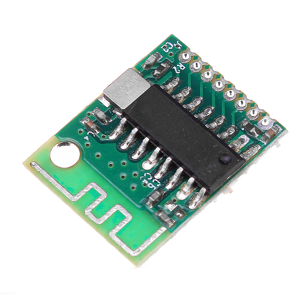
| JDY-18 Product introduction | |
| Model | JDY-18 |
| Working frequency band | 2.4G |
| Emissive power | Odb (maximum) |
| Communication interface | UART or IIC |
| Working level | 1.8V-3.3V |
| Working temperature | -40℃-80℃ |
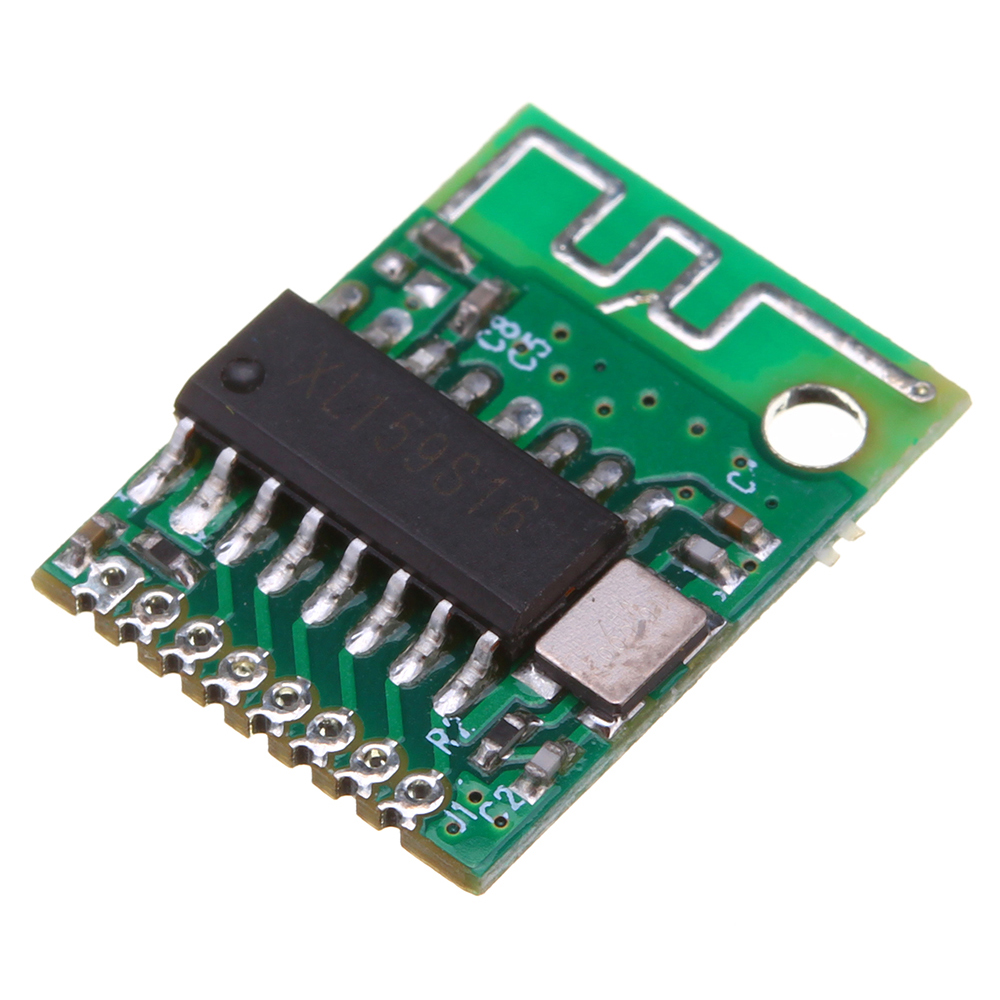
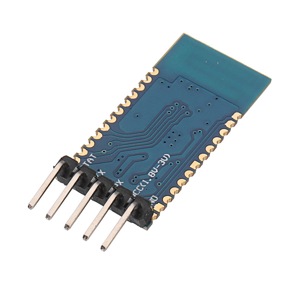
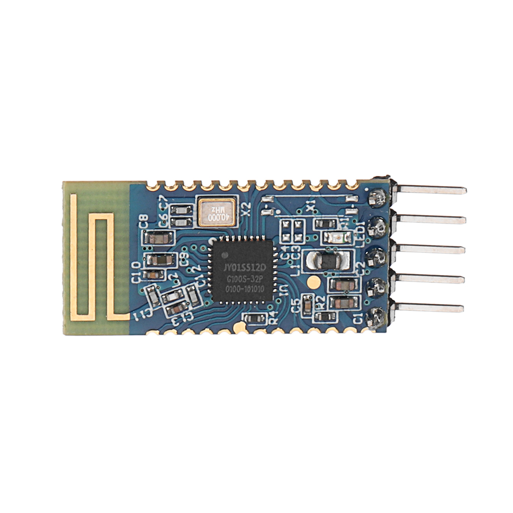
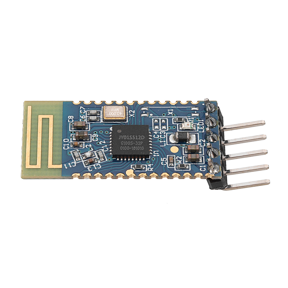
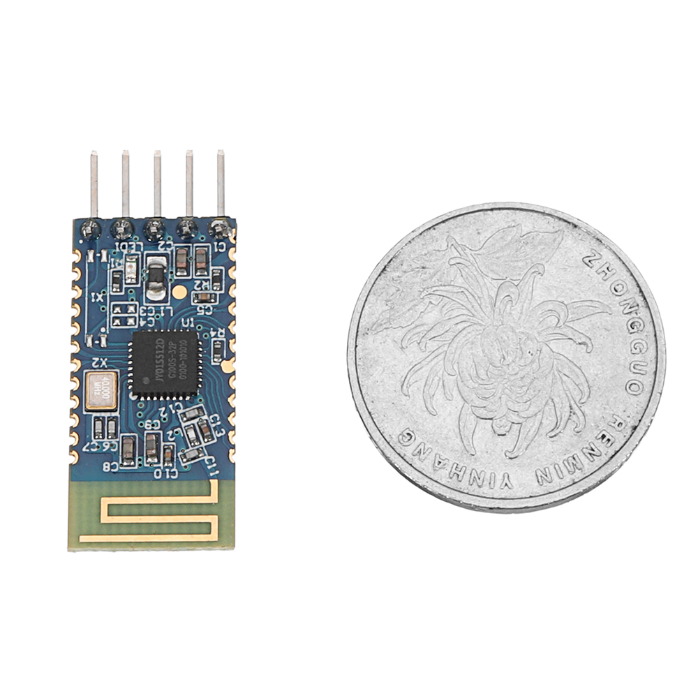
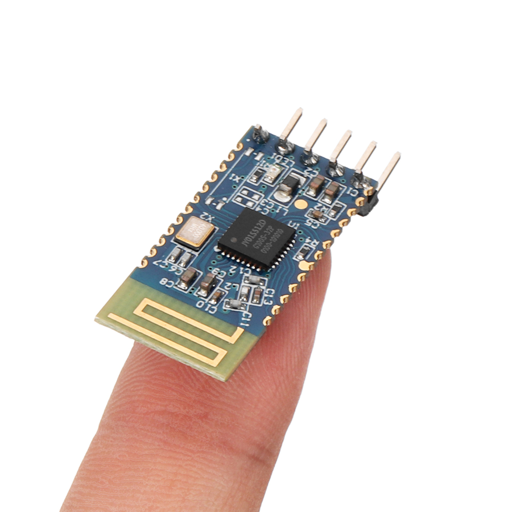
| Antenna | built-in PCB antenna |
| Broadcast instruction | Board broadcast indicator LED lamp |
| Reception sensitivity | -97dbm |
| Transmission distance | 60m |
| Bluetooth version | BLE4.2(compatibleBLE4.0,BLE4.1) |
| Transmission rate | 115200 bps/s |
| Wake-up state current | 4.9mA (broadcast) |
| Shallow sleep state current | <300uA (broadcast) |
| Deep sleep current | 0.8uA (broadcast) |
| Instruction parameter preservation | Parameter RTD set off electrical data to save |
| STM welding temperature | <300℃ |
| Working mode | Broadcast state | Current | Remark |
| Wake up | broadcast | 4. 9mA | Generally speaking with APP, it is suggested that broadcasting do not set M too long and too long to affect connection time. It is generally recommended between 100 and 500mS, such as fast connection and no demand for power consumption, and the shortest broadcast interval of M to the shortest distance. |
| Deep sleep free sleep | No broadcast | 1.38uA | |
| Shallow sleep has radio sleep | 100ms Broadcast interval | 280uA | |
| Average power consumption | 200ms Broadcast interval | llOuA | |
| 300ms Broadcast interval | 30uA | ||
| 400ms Broadcast interval | The following current is lower | ||
| 500ms Broadcast interval | |||
| 600ms Broadcast interval | |||
| 700ms Broadcast interval | |||
| 800ms Broadcast interval | |||
| 900ms Broadcast interval | |||
| 1000ms Broadcast interval | |||
| internal state of arousal | Self connection | 4. 93mA | You can check the AT+STARTEN instructions by connecting the PWRC pins with the AT pins or setting the M mode directly. |
| Sleep state | Self connection | 50uA |
| Pin | function | description |
| 1 | TXD_DC | SELECT boot for high power, this pin function is string n TXD SELECT boot for low power, this pin function is IIC DD |
| 2 | RXD_DD | SELECT boot for high power, this pin function is string n RXD SELECT boot for low power, this pin function is IIC DC |
| 3 | CTS | The effectiveness of serial flow control |
| 4 | RTS | The effectiveness of serial flow control |
| 5 | NULL | |
| 6 | NULL | |
| 7 | roil | PWM supports UART, IIC, and APP control |
| 8 | PWM2 | PWM supports UART, IIC, and APP control |
| 9 | PWM3 | PWM supports UART, IIC, and APP control |
| 10 | PWM4 | PWM supports UART, IIC, and APP control |
| 11 | RESET | Hardware reset pin |
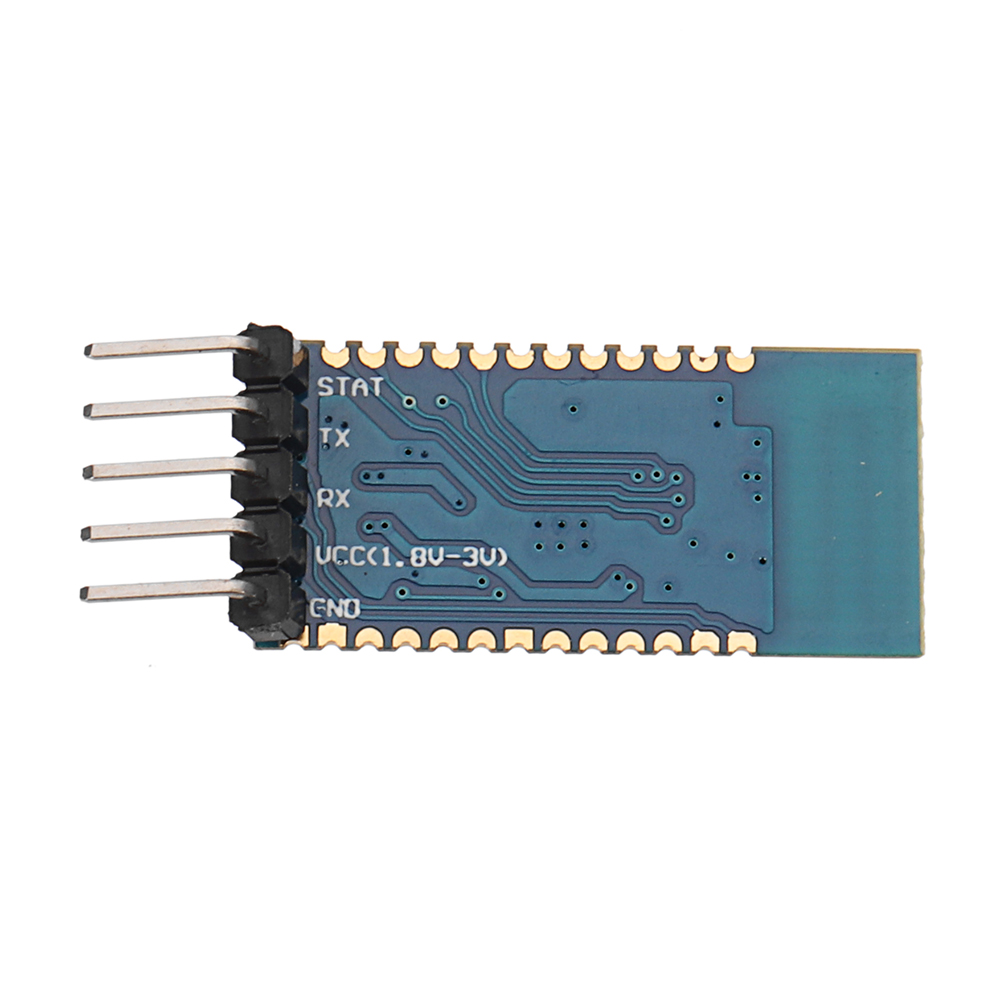
| 12 | VCC | Power supply (1.8-3. 3V) |
| 13 | GND | Power supply |
| 14 | PWRC | Down wake-up, when the AT instruction is needed in the connection state, the AT instruction mode can be expressed by keeping this pin low level, and the pin is AT instruction mode at high and low levels in the rice connection state. |
| 15 | ALED | Broadcast scintillation, frequent connection after connection (master and slave effectiveness) |
| 16 | STAT | UAKT communication mode: unconnected low level, high level after connection. IIC communication mode: no connection level, connect, disconnect or receive data will work in interrupt mode, interrupt down edge hold time 200ms |
| 17 | SELECT | UART or IIC select pin boot low level: IIC communication mode boot high level: UART communication mode. The default SELECT is suspended to high level: UART communication mode. When the user needs IIC, the SELECT pin should be grounded. |
| 18 | 103 | High and low levels can be controlled by APP |
| 19 | 102 | High and low levels can be controlled by APP |
| 20 | 101 | High and low levels can be controlled by APP |
| 21 | NULL | |
| 22 | NULL | |
| 23 | NULL | |
| 24 | NULL | |
| 25 | NULL |
Thông tin đang cập nhật
Vui lòng đăng nhập để đặt câu hỏi, hoặc nếu chưa có tài khoản, bạn có thể đăng ký nhanh.